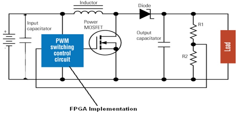
Project Objective: Switching control Circuit is the common block for Buck and Boost convertors above, our main focus of implementation is design of FPGA based Digital controller for a DC-DC convertor for Soc. The output voltage of a DC-DC convertor depends on the Switching control circuit (FPGA Digital controller-PWM). Hence our focus is to design a FPGA based Digital controller.
Buck and Boost convertor models will be first developed in MATLAB-SIMULINK, which will be based on PWM block. Verilog HDL coding will be done for the Digital Controller, synthesis will be done using Xilinx ISE, and Behavioral and Timing simulation will be done using Modelsim/Xilinx Simulator/Active HDL. After verification of code it will be downloaded onto a Spartan 3AN FPGA board. The pulse width output can be verified by an Oscilloscope and building an Analog Buck or Boost convertor circuit and connecting it to the FPGA Pin.
Tools: Xilinx ISE, Modelsim, Active HDL, MATLAB-SIMULINK
Hardware: FPGA Board, Buck Circuit, Oscilloscope


